Variable Orifice Air Valve Technology
Empirical research confirms in over a decade of results conducted by several researchers on a variety of conditions, that the most critical factor that determines the creation of surge and waterhammer on closure of the large orifice of an air valve, or the prevention thereof, is the size of the orifice at that critical point before closure. This is regardless of whether the system on which the air valves are employed is a gravity fed main or pumping system as the surge and waterhammer phenomena occur during initial filling as well as during column separation and the subsequent rejoining of water columns.
However, research and extensive computer modeling also indicates that the size of the orifice has to be balanced with the conditions within the pipeline system as too small an orifice may dampen waterhammer but increase mass oscillation (surge) as well as increase filling times for a pipeline whilst too large an orifice will induce waterhammer.
The demand for an air valve design with a multi adjustable orifice to address the above has been understood as far back as the early 1980’s but no successful, practical commercially produced air valve was designed until the advent of AIRFLO Variable Orifice Air Valve Technology.
AIRFLO Variable Orifice Air Valves incorporate a variable floating shuttle that automatically adjusts the discharge outlet of the valve to the conditions within the pipeline and provides the optimum orifice diameter at any given point during the performance of the pipeline to ensure effective air release whilst preventing waterhammer and substantially reducing mass oscillation.
AIRFLO Variable Orifice Air Valve Technology is a patented technology that represents a revolutionary way in the addressing of surge and waterhammer during the release of air. This technology effectively breaks away from the drawbacks and constraints of the surge damping function of other air valve technologies.
The most significant advancement is the fact that this design does not have a stationary and standardised orifice and is sensitive to the air outflows of the pipeline. This smooth transition from one differential pressure to the next and the constant adjustment of the orifice size and therefore the backpressure and the slowing down to the advancing water column as the outflow velocities increases is of major benefit to the pipeline designer as it takes away the guess work of whether the orifice is either too small or too large under varying pipeline operating conditions
The action of the AIRFLO Variable Orifice is such that it will readjust itself under pump trip and column separation conditions thereby allowing for effective air release whilst reducing the magnitude of the surge as well as reducing the amplitude and time period of the pressure wave. This brings the pipeline to a steady state much more rapidly and smoothly without damage to system.
AIRFLO Variable Orifice air valve technology is a substantial advancement into air valve technology and has moved the performance criteria and the technology for air valves ahead in a significant way in essence setting the bench mark for measuring future advancements in air valve technologies.
Read more
AIRFLO Recommended Air Valve Chamber Design
A typical Air Valve chamber should have the following considerations:
Valve Chamber
A well designed valve chamber is of importance and should be designed with easy access to the valve for installation and subsequent maintenance.
Good support is required in the event of the chamber settling. It is recommended that a layer of stone be placed under the pipe for drainage purposes.
When utilising concrete rings, utilise rings with a 1.5m diameter and with a concrete cast floor with a minimum of a 800mm opening for the air valve accumulator (see diagram 2)
Vents
Two vents should be installed to prevent pressure build up in the valve chamber and facilitate air circulation in the chamber. Further, the diameter of each vent should be equal to or greater than the size of the air valve, a mesh with a large aperture should be placed on the inlet to allow for effective air intake but prevent vermin from entering the valve chamber.
Isolators
Resilient Seated Gate Valves (RSV) are the most suitable isolators for PN16 and PN25 pressure ratings and for air valve sizes of DN80 and larger. Butterfly valves should be avoided as isolators for air valves because they present a restriction in flow and may cause turbulence in flow towards the air valve.
Wedge gate valves should be avoided as isolators for PN40 and higher pressure ratings. It is recommended in these applications that single offset ball valves be used.
Full bore ball valves are cost effective and highly suitable isolators for DN25 and DN50 air valves
It is important that an air valve isolator is fully opened during commissioning to prevent turbulence in flow towards the air valve.
Air Valve
An air valve should always be correctly sized for the application. It is recommended for large applications to install two smaller air valves per air valve position in place of only one large air valve. This implies that the pipeline will always be protected to a degree if one of the air valves fails for whatever reason.
It is sometime requested that an air valve be supplied with bleed cock. In older designs, the bleed cock was essential to determine if the air valve is working by opening up the bleed cock periodically to see if air or water is released from it. With the AIRFLO Variable Orifice design, the purpose of the bleed cock serves only as a possible point to measure pressure as the design ensures effective air release regardless of the application.
Riser
The riser towards the air valve should be equal to the air valve nominal size. Some research was conducted in the 1990’s regarding the impact of the riser length on the surge and waterhammer phenomenon. It is recommend that the riser not exceed more than 500mm in height
Air Valve Accumulator Tee
An air valve accumulator is imperative for every air valve in order to facilitate efficient air valve operation as it provides a discontinuity in flow thereby allowing the air to accumulate underneath the air valve for effective release. The air valve accumulator tee should have a vertical branch that is at least ½ the diameter of the pipeline. A diameter of up to 1/3rd the diameter of the main pipeline diameter is acceptable as the absolute minimum size for the accumulator.
The vertical branch should be flanged for fitting of the riser to it.
Flange Adaptor
In the case of flanged tee where the horizontal branches are flanged, it is recommended that at least one flange adaptor is attached to the tee in the direction of flow. This will assist in the ease of installation.
Coupling
It is recommended that every air valve chamber be fitted with at least two couplings – one on either end of the chamber. The purpose of the couplings is to assist should there be any settling of the chamber. Should the soil be unstable and a large amount of settling is expected then, it is recommended that four couplings be utilised with at least two couplings on each end.

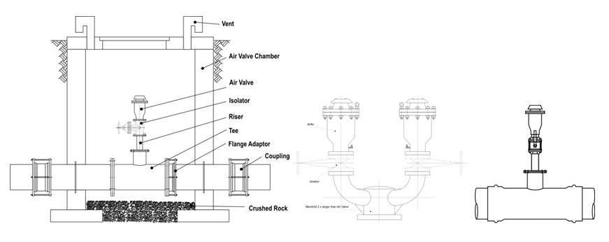
Fig.1 The picture on the left is for A recommended Typical Air Valve Chamber the picture in the recommended installation of 2 or more air valve per chamber for large diameter pipelines. The picture on the right indicates a typical small diameter installation utilising a screwed inlet for the air valve with a full bore ball valve as an isolator.
Read more
Training
Air valves generally constitute a small cost to the total value of a pipeline project but if incorrectly selected, sized and positioned, could result directly or indirectly into a host of pipeline destructive phenomena including surge, waterhammer, corrosion and high energy consumption. The last 20 years has seen a great amount of research on air in pipelines and the characteristics of air valves.
AIRFLO introduces a free Continuous Development Points (CDP) bearing course that takes and in-depth look at issues such as energy consumption, vacuum and surge and waterhammer as it relates to air valve selection, sizing and positioning and leaves the delegate with the tools to size and position from 1st principles and a better understanding of the available air valve technologies and their impact on the surge and waterhammer phenomena. The ultimate aim of the course is on the most economic, efficient and effective employment of air valves on pipelines.
Course Summary Review:
- The behaviour of air in pipelines
- A review of air valve technology
- Air valve sizing and positioning theory and practice
- Air valves sizing and pipeline materials selection
- Air valves and surge and waterhammer
- Air valve chamber design
We will conduct a full seminar at your convenience and on your premises at no cost or obligation. Contact us
Read more